
# FPC Coverlay Guide: Materials, Thickness, Openings and Design Tips
Coverlay is one of the most important protective materials used in FPC flexible circuit manufacturing.
Although it may look similar to solder mask on a rigid PCB, FPC coverlay has a different structure and plays an important role in flexibility, insulation, mechanical protection and long-term reliability.
Choosing the correct coverlay material, thickness and opening design can help reduce manufacturing problems and improve the performance of the finished flexible circuit.
In this guide, we explain the main factors buyers and engineers should consider when specifying FPC coverlay.
What Is FPC Coverlay?
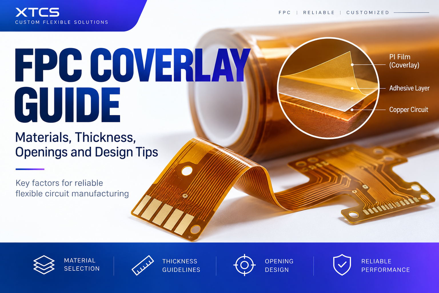
FPC coverlay is a protective film laminated onto the copper circuit of a flexible printed circuit.
A typical coverlay structure consists of:
- Polyimide (PI) film
- Adhesive layer
- Openings for pads, fingers and soldering areas
The PI film provides insulation and mechanical protection, while the adhesive bonds the coverlay to the flexible circuit.
After lamination, the coverlay protects the copper traces from oxidation, contamination, scratching and mechanical damage.
Why Is Coverlay Important in Flexible Circuits?
Flexible circuits are designed to bend, fold or move during assembly or operation.
Because of this, the protective layer must also maintain good flexibility.
Coverlay helps provide:
- Electrical insulation
- Copper trace protection
- Mechanical protection
- Improved bending reliability
- Protection from moisture and contamination
- Stable performance during assembly
For many dynamic or high-flex applications, traditional rigid PCB solder mask may not provide the same mechanical flexibility as PI coverlay.
Common FPC Coverlay Materials
Polyimide is the most commonly used coverlay material for flexible circuits.
A typical FPC coverlay contains a PI film combined with an adhesive layer.
Common PI film thicknesses may include:
- 12.5 μm
- 25 μm
- 50 μm
Adhesive thickness can also vary depending on the copper thickness, circuit structure and application.
The final selection should be based on the complete FPC stack-up rather than choosing the PI thickness alone.
For example, thicker copper or larger circuit height differences may require a different adhesive thickness to achieve reliable bonding.
PI Thickness and Flexibility
Coverlay thickness directly affects the flexibility of the finished FPC.
In general:
Thinner coverlay can provide better flexibility and a smaller bending radius.
Thicker coverlay can provide stronger mechanical protection but may increase the overall stiffness of the circuit.
For applications that require frequent bending, the complete structure should be evaluated together, including:
- Base PI thickness
- Copper thickness
- Adhesive thickness
- Coverlay thickness
- Number of copper layers
- Stiffener structure
Simply reducing one material thickness does not always guarantee better bending reliability.
Coverlay Opening Design
Coverlay openings expose the areas that need electrical connection or soldering.
Typical exposed areas include:
- Component pads
- Connector pads
- Gold fingers
- Test points
- Soldering terminals
The coverlay opening is normally designed slightly larger than the copper pad.
This provides manufacturing tolerance for coverlay alignment and prevents the coverlay from partially covering the soldering area.
However, excessively large openings can reduce insulation and expose more copper than necessary.
The correct opening size should consider:
- Pad dimensions
- Coverlay registration tolerance
- Copper spacing
- Assembly process
- Connector requirements
- Soldering method
For fine-pitch designs, coverlay opening accuracy becomes especially important.
Coverlay Around Gold Fingers
Gold finger areas normally require precise coverlay openings.
The coverlay should protect the circuit while keeping the contact area fully exposed.
Poor opening design may cause problems such as:
- Partial coverage of the contact area
- Reduced connector contact reliability
- Insufficient insulation between adjacent traces
- Difficult assembly
If an FPC uses fine-pitch gold fingers, the Gerber files should clearly define the coverlay opening and contact area.
Coverlay vs Solder Mask
Coverlay and solder mask both protect copper circuits, but they are not identical.
Coverlay is usually made from polyimide film and adhesive and is widely used in flexible circuit structures.
Solder mask is applied as a coating or ink and is more commonly associated with rigid PCB manufacturing.
For FPC applications, coverlay is often preferred because of its mechanical flexibility and reliability during bending.
However, some flexible circuit designs may also use flexible solder mask depending on the application, cost target and manufacturing requirements.
The final choice should be evaluated according to the circuit structure and operating conditions.
Important Factors When Selecting Coverlay
Before placing an FPC order, several parameters should be confirmed.
1. Copper Thickness
Copper thickness affects both circuit current capacity and overall flexibility.
It also affects how much adhesive may be required to properly encapsulate the circuit pattern.
2. Overall FPC Thickness
If the project has a strict total thickness requirement, the base material, copper, adhesive and coverlay must all be considered together.
3. Bend Area
The location of the bending area is very important.
Pads, vias, stiffener edges and abrupt thickness changes should be carefully evaluated around high-stress bend areas.
4. Assembly Method
The coverlay opening design may be different for hand soldering, SMT assembly, connector insertion or gold finger applications.
5. Environmental Requirements
Temperature, humidity, repeated bending and mechanical stress can all influence the coverlay material selection.
Common Coverlay Design Problems
Some FPC manufacturing problems are related to coverlay design rather than the copper circuit itself.
Typical issues include:
- Coverlay opening too small
- Coverlay opening too large
- Poor alignment between coverlay and pads
- Insufficient adhesive coverage
- Coverlay bubbles
- Delamination
- Excessive stiffness in bending areas
- Coverlay edge too close to critical circuit features
Many of these issues can be identified during engineering review before production.
What Files Should You Provide for FPC Manufacturing?
For a faster quotation and engineering review, it is recommended to provide complete production files.
Typical information includes:
- Gerber files
- FPC dimensions
- Layer count
- Copper thickness
- Finished thickness
- Surface finish
- Coverlay requirements
- Stiffener requirements
- Quantity
- Special process requirements
If the FPC includes connectors or SMT assembly, assembly information should also be provided.
Complete files help the manufacturer evaluate the coverlay structure, manufacturing tolerance and process feasibility more accurately.
Engineering Review Before Production
Coverlay should not be considered as an isolated material.
It is part of the complete FPC mechanical structure.
Before production, the manufacturer should review the relationship between:
- Copper traces
- Pads
- Vias
- Coverlay openings
- Bend areas
- Stiffeners
- Connectors
- Overall thickness
For customized FPC projects, engineering review is especially important when the design includes fine-pitch contacts, repeated bending, unusual shapes or strict thickness requirements.
Conclusion
FPC coverlay has a direct impact on circuit protection, flexibility, assembly and long-term reliability.
When selecting a coverlay structure, engineers should consider not only PI thickness but also adhesive thickness, copper thickness, opening design, bending requirements and the complete FPC stack-up.
A well-designed coverlay can help reduce production risk and improve the reliability of the finished flexible circuit.
If you are preparing a custom FPC project, you can send your Gerber files, dimensions, layer count, quantity and material requirements for engineering review and quotation.